Service Definition
Variable speed limit (VSL) system consists of variable speed limit signs, maximum, minimum or advisory, to guide drivers to travel at a speed suitable to the prevailing traffic or weather conditions , in some cases supported by Speed Enforcement (SE), which mostly uses cameras to identify speeding vehicles and/or drivers.
Functional Requirements
Functional architecture
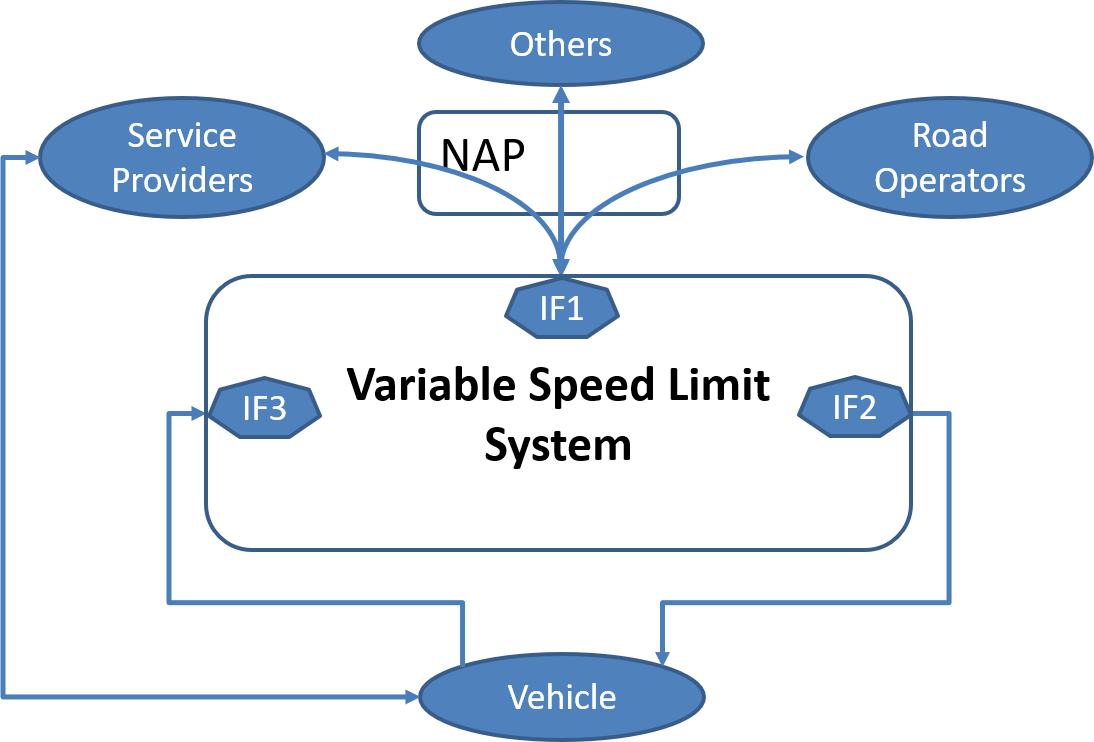
The following figure shows the typical functional architecture of a VSL system. Blue arrows show possible interfaces to other services.
Functional requirements and advices
Functional requirements:
- FR1: Functional decomposition and the provision of standardised interfaces should be carried out to ensure interoperability in cases where the service is carried out by more than one organisation (and is in any case recommended to be prepared for an easy functional decomposition, as could be the case in the future). Control and algorithms may be done through local (roadside) or central systems.
- FR2: Sensors must be adapted to the service and give input to the control system. Exceptions: For systems using clock and/or calendar control, sensors are replaced by the system clock. For manually controlled systems at road works, sensors are usually replaced by a keypad (local control unit) or similar.
Note: Systems may include both manual and automatic functions as well as several types of sensors. This requires well defined hierarchical rules and priorities. - FR3: Automatic and semi-automatic systems should contain models and algorithms that calculate the speed limit and transmit it to the signs. These models and algorithms can be implemented in a central control system or at the roadside.
- FR4: The signs must display the speed limit, that the control system has requested, and functionality must be monitored continuously.
- FR5: If VSL systems interact with other services like hard shoulder running, dynamic lane management or HGV overtaking ban (or adjacent VSL systems), interfaces should be implemented either at roadsides or in central control systems. In practice, this can often be internal interfaces in the same system.
- FR6: Signs should report to the control system if message activation was successful or not and possible error messages.
- FR7: Traffic Management Centre Operators should be trained in supervising the system, be able to control the system manually and override automatic operation. Exception: Local VSL systems sometimes can operate independently and need no supervision regarding current signposted speed limits.
- FR8: The central control system should have the ability to supervise and control each individual system. Exception: Local VSL systems sometimes can operate independently and need no supervision regarding current signposted speed limits.
- FR9: VSL systems should have a log that stores data about signposted speed limits, error messages, etc.
- FR10: To avoid unanticipated deceleration, gradual speed reductions should be shown as 20-40 km/h increments, dependent on operating environments, context, speed and road topology (note: 20 km/h reduction between two gantries is common practice on motorways).
- FR11: Detector data updating frequency should be adapted to the required response times. For instance, a normal updating frequency for traffic data is from real time to one minute.
- FR12: The systems should have predefined handling of situations like power failure, disruptions in communications and other functional problems to avoid functional inconsistencies in the service. System parameters and error states should be disseminated in real time to on duty staff.
Functional advices:
- The control algorithms shall result in speed limits that are relevant to achieve the desired effects and responds quick enough in critical situations
- The algorithms shall be constructed in an appropriate and stable way to avoid unnecessary switching of the speed limits.
- Automatic control shall be used whenever possible. You may also consider the option of using a semi-automatic mode where you set the maximum speed limit manually but let the system vary the displayed speed limit up to this threshold. This can be especially useful for long road works.
- When a VSL system is used to decrease the risk of rear-end collisions due to congestion, detector spacing shall be adequate to the function. The distance between detector and gantry needs to be adjusted.
- The components in roadside equipment have to be of the correct environmental class to cope with the environmental conditions. For maintenance reasons, it is an advantage if the components of the systems are easy to reach and replace.
- When VSL is supplemented by speed enforcement, the monitoring technology used by private as well as public road operators, which generates evidence of speeding, have to meet the national legal requirements.
- A general rule to achieve a good understanding and observance of VSL is that the speed limits have to be relevant for road users. Not only to achieve the individual but especially the collective relevance. This sets the requirements for data collection and control principles. It is relatively easy for the driver to understand that the speed limit is reduced when there is congestion or bad weather, but it is more difficult to communicate speed reductions due to, for example, environmental reasons. Therefore, road authorities can consider including a warning sign with a pictogram or a text showing the reason for the displayed speed limit.
Interface requirements
Interface requirements:
- IF1: The Speed control / Speed limit information structure must include the following elements:
- maximum Speed Limit itself
- the linear location of the Speed Limit
- where necessary, the type of vehicle concerned by the Speed Limit
- IF2: The Speed control / Speed limit information structure must include the following elements:
- the current setting of a variable Speed Limit sign (gantry)
- the location of the sign (gantry) and the stretch of road to the next sign (gantry)
- where necessary, the type of vehicle concerned by the Speed Limit (text)
- IF3: The Probe Vehicle Data (microscopic traffic situation) information structure must include the following elements
- Postion/trajectory
- Speed
- Acceleration
Organisational Requirements
Organisational advices
- The responsible organisation has to establish a good cooperation with the police and good communication with the public for the reasons and benefits of VSL. This is a key to success and encourages a positive attitude from drivers.
- VSL is mostly a concern of the Road operators (road authorities and motorway companies and its subsidiaries). However, these stakeholders can also be considered:
- Municipalities and cities: At boundaries between state and municipal roads or when these systems influence traffic flow on municipal roads. Municipalities and cities may also implement VSL on their own networks.
- Public transport authorities and operators: When these systems influence accessibility and schedules for public transport. It is also possible to consider priority for public transport in separate lanes in conjunction with VSL.
- The Police: To enforce the speed limits for better compliance by road users. The police are generally an important partner when speed limits are enforced using automatic speed enforcement systems. Depending on national regulations, the police may also need to accept VSL projects formally.
- A cost-benefit analysis, as well as an analysis of the achieved effects in relation to the objectives, can be carried out when new VSL systems are deployed, unless similar projects already have been thoroughly evaluated. For suggestions about evaluation, see part B.
Common Look & Feel requirements
Common look & feel requirements:
- CL&FR1: Mandatory variable speed limits (Maximum) should be displayed in one of the following ways:
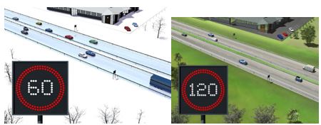
- Discontinuous signs: White, off-white or yellow figures on a black background enclosed by a red ring. Discontinuous VMS can also be used without colour inversion if national regulations allow or require this.
- Continuous signs: Sign surface similar to fixed mandatory speed signs according to national regulations.

Reference to the Vienna convention: Sign C14.
- CL&FR2: Variable speed limits (Minimum) should be displayed in one of the following ways:
- Discontinuous signs: White, off-white or yellow figures on a black background enclosed by a whited ring. Discontinuous VMS can also be used without colour inversion if national regulations allow or require this.
- Continuous signs: Sign surface similar to fixed mandatory speed signs according to national regulations.
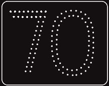
- CL&FR3: Advisory dynamic speed signs should be displayed in one of the following ways:
- Discontinuous signs: White, off-white or yellow figures on a black background. The sign can have a white rectangular border, but no red ring. Discontinuous VMS can also be used without colour inversion if national regulations allow or require this..
- Continuous signs: Sign surface similar to fixed advisory speed signs according to national regulations
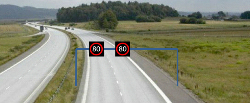
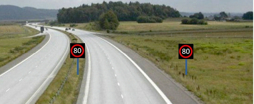
- CL&FR4: Signs should be located either above the carriageway or on the verge of the road. If signs are located on the verge, they should be signs on the near side of the road with possible supplementary signs to the offside. If there is more than one lane in the direction of travel, it is recommended to have signs on both sides.
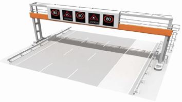
- CL&FR5: If signs are mounted above the carriageway, you may have one speed limit sign above each lane (which apply only to each lane) or a single speed limit sign integrated in a larger VMS which is valid for all lanes.
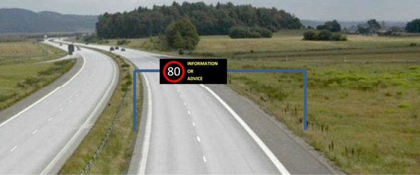
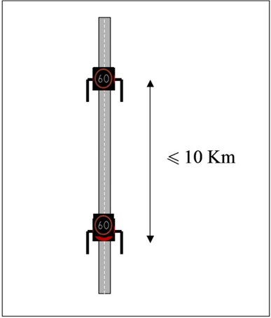
- CL&FR6: Speed limits should be repeated at least after every entry slip road, and the distance should never exceed 10 km on long stretches or according to national guidelines and operating context.
- CL&FR7: It should be obvious to the drivers when a section with VSL ends and what the valid speed limit is after that. Normally this is done using fixed speed limit signs.
- CL&FR8: To avoid driver confusion about which speed limit is valid, fixed and variable speed limit signs should never be mixed along a particular roadway segment.
- CL&FR9: For certain roadway segments speed limit signs may be active only when a reduced speed limit is set. In other cases, they may be blank. In some circumstances this makes it easier for the drivers to notice conditions that require a lower speed.
Common look & feel advices:
- Yellow flashing lights can be added to increase visibility. In Motorway Control Systems yellow flashing lights can be used to alert the driver that he/she enters a section with a lower speed limit.
- Signs mounted above each lane can display different speeds for respective lanes, but only in limited cases and after proper testing and evaluation. In these cases, the greatest difference in speeds between adjacent lanes shall not exceed 20 km/h. This requires that the traffic management system algorithms perform separate calculations for each lane while respecting a maximum speed difference of 20 km/h between adjacent lanes throughout the length of the roadway segment.
- Side mounted VSL can remain in operation also when single lanes are closed. On the contrary, portal mounted VSL over closed lanes can be switched off, unless they are used in a multilane control system where a red cross is displayed.
- It is common that VSL is integrated in motorway control systems, where the variable speed limit signs are mounted above the carriageway. In these cases, VSL can be combined with, e.g. lane control and warning signs. The requirements and advice regarding VSL in this guideline are still applicable but need to be combined with requirements and advice from other guidelines like TMS-DG01 (Dynamic Lane Management) and TMS-DG05 (Incident warning and Incident Management).
- For weather controlled VSL, many different types of sensors can be used and in some cases combined with weather forecasts. Example of sensors:
- Air temperature, air humidity/dew point, road surface temperature
- Wind, speed and direction oVisibility
- Freezing point of liquid on the road
- Road surface status (i.e. dry, wet, ice, snow; thickness may be included)
- Precipitation intensity
- For weather controlled VSL, automatic control with supervision from TMC operators ought to be used as much as possible. Much effort needs to be put into design of the weather control model and its algorithms. Note: National legislations may prevent road operators from using automatic weather controlled VSL.
VSL at intersections
-
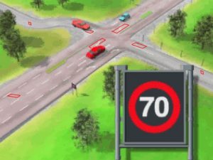
- For VSL at intersections, detectors for vehicle passage and presence are used. Passage detectors are used to activate the system, when vehicles approach the intersection. Presence detectors keep the system active when vehicles wait at the intersection. Detectors can be placed both on incoming secondary roads and the left turning lane (when driving on the right) on the primary road (see example in the figure below).
- For VSL at intersections, detectors for vehicle passage and presence have to be used. Passage detectors are used to activate the system, when vehicles approach the intersection. Presence detectors keep the system active when vehicles wait at the intersection.
- For VSL at intersections, detectors can be placed both on incoming secondary roads and the left turning lane (when driving on the right) on the primary road (see example in the figure below).
- For VSL at intersections, reduced speeds have to be displayed on the primary road when vehicles approach the intersection from the secondary roads and also when vehicles are present in the left turning lane on the primary road. In the latter case, reduced speed needs to be displayed only in the opposite direction. Manual override is often possible in case of accidents or road works.
VSL on motorways
-
- For VSL on motorways, sensors are usually placed at each sign gantry. Inductive loops and microwave are commonly used technologies. Also video, laser, light barriers and piezoelectric sensors are used.
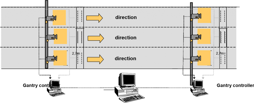
- VSL on motorways are often automatic and based on sensor data. Manual override is used mainly in case of accidents or road works or, in wintertime, warnings concerning slippery and snowy roads. The algorithms should be designed both for increased throughput and safety (“queue warning function”).
Required Standards and Specifications
Information provision standards
- IPS1: Speed limit information (see IFR1) must be profiled based on CEN/EN 16157-3 using the DATEX II Recommended Reference Profile for Variable Speed Limits
- IPS2: Speed limit information (see IFR2) must be provided based on ISO 19321 using the C-ROADS C-ITS Infrastructure Functíons and Specifications for the In-Vehicle Signage service
- IPS3: The Probe Vehicle Data (microscopic traffic situation) information (see IFR3) must be provided based on ISO 19321 and the C-ROADS Common C-ITS Service Definitions Probe Vehicle Data (PVD) v 0.8 (not yet released)
Variable Message Sign standards
- SS1: Discontinuous signs (i.e. LED) must follow the European standard EN 12966:2014+A1:2019 or their national counterparts. Continuous signs (retro-reflective, i.e. prism signs) must follow the European standard EN SS-EN 12899-1:2007 or their national counterparts where applicable.
Note: The standards allow several levels of performance to be selected due to i.e. the environment where the signs are used.
Standards for Fixed traffic signs
- EN 12899-1:2007 Fixed, vertical road traffic signs – Fixed signs. This standard should be used for continuous (retro-reflective) variable signs, like prism signs.
Need for Additional Standards or Specifications
None
Level of Service Definition
Level of Service Criteria
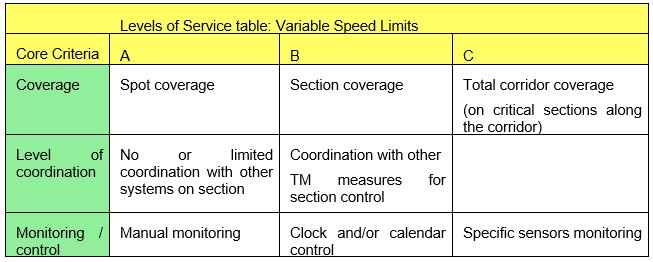
Coverage
- A – spot coverage: The VSL system covers only a short stretch of road where specific conditions prevail, for example. hazardous intersection.
- B – Section coverage: The VSL system covers a longer stretch of road, but does not cover an entire corridor. A corridor in this case is the total road from one important point to another, e.g. between two cities.
- C – Total corridor coverage: The VSL system covers an entire corridor as described above.
Level of coordination
- A – No or limited coordination with other systems on a section. The VSL system does not operate in a coordinated way with other Traffic Management measures like hard shoulder running or lane signals.
- B – Coordination with other TM measures for section control: The VSL system is coordinated with other measures, often integrated in a Motorway Control System.
Monitoring and control
- A – Manual monitoring: Traffic Management staff change the speed limit manually when there is a need. The operators can either discover the problem through a CCTV system or get information from partners, like the police and rescue services.
- B – Clock and/or calendar control: The speed limit is set automatically due to time of day and/or year. This option is most suited for situations where you have daily or seasonal recurring problems.
- C – Specific sensors monitoring: Automatic control with sensors which detect the situation that calls for a reduced speed limit. This is generally the best solution, since it is not dependent on manual supervision and the displayed speed limit is in most conditions seen as relevant by the drivers.
Level of Service Criteria related to Operating Environment
Level of service requirement:
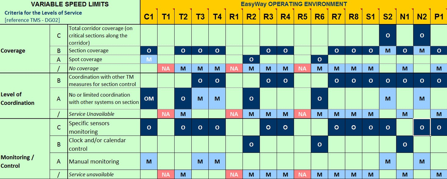
- LoSR1: In the case that pre-deployment surveys / evaluations provide the necessary evidence to proceed with the deployment of the ITS-service “Variable speed limits”, the minimum and optimum LoS should respect the following Level of Service to Operating Environment mapping table.
Note: The Level of Service to Operating Environment mapping table is not an outcome of a specific scientific analysis but an expert view output.